-40%
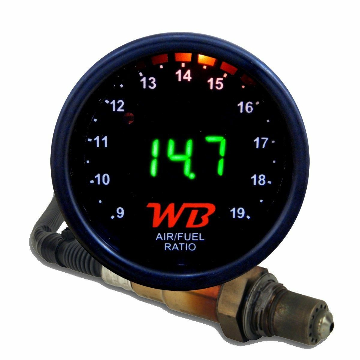
APSX V2 Anti-Glare D2 Digital Wideband O2 AFR Gauge & Sensor Kit Black & GREEN
$ 78.11
- Description
- Size Guide
Description
APSX D2 Digital Wideband O2 Air Fuel Ratio (AFR) Complete Controller Gauge Kit (Including LSU 4.2 Oxygen sensor)BLACK Face Plate & Green LED Display (V2 now comes with Anti-Glare Face Design)
Please watch the following video for Product Comparison (with other brands):
https://youtu.be/o_pGifwvm8E
APSX Wideband Controller has been designed to exceed the performance of similar devices, while offering lower cost.
It is easier to install. When you make modifications on your engine, accurate air/fuel ratio data is so important. If your
engine runs rich, it can cause a loss in power. Also if it runs lean, it may cause serious engine damage. It will give you
time to shut down your engine before damage occurs.
This kit includes: D2 52mm gauge assembly, pre-assembled output and oxygen sensor cables with connectors and Bosch LSU4.2. D2 assembly includes clear lens, black bezel, face plate, bung and LED display.
It is smaller and more cost effective than other leading brands in the market today. It comes with benefits such as:
1 – Less wiring – no D1 controller required
2 – Simple installation – no D1 controller required
3 – Bright LED Display and supports Four types of fuel (E85, Diesel, Gasoline and Methanol) and lambda display
4 - Sweeping LED "needle" indicator from rich (green) then normal (orange) to lean (red)
5 - Fail safe connector - it is not possible to make a wrong connection
6 - Multiple outputs for digital (to PC), analog (to data logger / EMS), narrow-band for simulation and extra switch options
7 - No need a PC or tablet for programming upper/lower limits and other settings
Less Wiring & Simple Installation
Since there is no D1 controller required, there is only Bosch LSU4.2 Wideband Oxygen Sensor (17014) and output cables to be connected.
OUTPUTS
1 – Analog 0-5V linear output
for engine management systems (EMS) and data loggers (MegaSquirt)
Lower and upper limits are 9 AFR and 19 AFR (0V = 9 AFR, 5V = 19 AFR)
2 – Digital output
is 9600 8N1 serial that can be connected to your PC
3 – Simulated NB output
Both EFI and carburated applications are ok. Soft Start technology protects oxygen sensor for damages.
*** The low and high limits for analog and simulated NB (Narrow-band) can be modified using the setup procedure.
WIRING
APSX D2 has a 4ft output cable (5 cables / green-white-red-orange- black) as shown in diagram above.
Red power cable goes to 12V source in your vehicle.
Black cable goes to a grounded source such as battery ground (-) post.
Green digital output is 9600 8N1 serial that can be connected to your PC.
If you want to connect other devices such as data loggers or AFR gauges, you can use white analog cable for 0-5V output.
Orange narrow-band cable is for simulated NB.
The sensor cable (8ft) should be routed in a way so that there would not be any contact with the exhaust piping and other extreme heat sources to prevent damage to the wiring.
GUIDELINE FOR THE LOCATION OF THE OXYGEN SENSOR
Weld the bung at least 24” downstream of exhaust port outlet or 24” after the turbocharger. It should always be before the Catalytic Converter. Also it should be before the X or H pipe if there is. Bung should be welded on the upper section which is located between 10AM or 2AM clock positions. Please check your vehicle for exhaust leaks, camshaft overlap and open exhausts because those would cause false lean readings. Not following these directions may result in premature failure of the sensor.
WARNING!
Oxygen sensor can get very hot when powered. Keep the oxygen sensor powered when the engine is running to prevent damage to the O2 sensor.
CALIBRATION -
Already Calibrated (Plug & Play Installation)
The O2 sensor should be exposed to free air for the first time calibration. Hold the button back of D2, you will see display unit counting from 1.1 to 1.6.
Hold the button until you see 1.6 blinks and release it to complete the calibration. This should take less than 60 seconds.
Once it calibrated, display reads 19.0. You can now connect the O2 Sensor onto the exhaust pipe. See the guidelines on the left. For the factory settings, disconnect power, hold the switch while turning the power on and wait for 3 blinks. You should re-calibrate after this action.
Calibrated for the enclosed sensor. For the
Calibration Video
please visit "widebandapsx" at our official YouTube account.
INSTALLATION PROBLEMS?
Please perform a bench test before contacting with us. Please also use the battery as your ground source with an 5A fuse to be on the safe side. If you are having 8.88 reading problem, there might be a discontinuity on your chassis and can not be used for grounding:
a. Place all parts of the kit on a bench/table
b. Make connections by using a reliable 12V battery or other power source
c. Check the display to see if it shows logical outputs while you place the oxygen sensor into a gas soaked towel or paper towel. You can even use a lighter gas
d. Readings should change between 9 and 19 AFR
e. If not, please send us the unit for inspection to repair or replace
PROGRAMMING
Depending on when you release the button on D2 after holding it, you can modify different settings.
1 – Set the fuel type (1-Lambda, 2-E85, 3-Gasoline, 4-Diesel, 5-Methanol). See the chart and table above for fuel types
2 – Set NB lower limit
3 – Set NB upper limit
4 – Set Analog lower limit (Range 7-25 AFR/Default is 9 AFR)
5 – Set Analog upper limit (Range 15-25AFR/Default is 19AFR)
6 – Calibration (Calibration range we have seen among the Bosch LSU4.2 sensors 70-130)
A 0: Power ON
A 1: Sensor ON
14.7 AFR or Stoich: Cruising or on Neutral gear
19 AFR or Max range: On gear and gas pedal is not pushed
TERMS OF USE
APSX WIDEBAND does not guarantee the product functionality with any ECU, data logger or other devices that uses the output signals. Implementation and integration of the product with any other device(s) must be done at your own risk. Improper installation and usage may lead to engine damage. Mount and install the product in a location where it does not obstruct the driver’s view and/or ability to safely control the vehicle.
LIMITED WARRANTY
APSX WIDEBAND warrants this product to be free from defects for 12 months from the date of purchase. Oxygen sensors are excluded from stated warranty. APSX WIDEBAND’s obligation under warranty shall be limited to repairing or replacing, under the discretion of APSX WIDEBAND, any part proven defective. This warranty is limited to the repair or replacement of parts in the manufactured good and the necessary labor done to affect its repair or replacement.
SERVICE UNDER WARRANTY
In the unlikely event that your APSX WIDEBAND hardware should fail during the warranty period, a Return Material Authorization number (RMA) must be first retrieved from APSX WIDEBAND. Support can be contacted through email: at wide-band.com. All serviceable goods must be packaged securely, RMA number, with all shipping charges prepaid and shipped to APSX WIDEBAND. Goods returned under warranty must be received by APSX WIDEBAND within ten (10) business days after the RMA number has been issued. Goods received after this period is subject to fees for the service of repair or replacement.
DISCLAIMER
APSX WIDEBAND shall not be liable for direct, special, incidental, or consequential damages resulting from any legal theory including, but not limited to, lost profits, downtime, goodwill, damage, injury to persons, or replacement of equipment and property due to improper installation, integration and/or misuse of any APSX WIDEBAND’s product(s). This warranty applies to the original purchaser of product and is non-transferable. All implied warranties shall be limited in duration to the said 90 day warranty period.
CONDITIONS FOR WARRANTY VOID
This warranty shall terminate and APSX WIDEBAND shall have no obligation pursuant to it if (1) your product has been modified or repaired in a manner not previously authorized by APSX WIDEBAND in writing,, (2) your product was subjected to accident, abuse, shipping damage, or improper use; (3) your product was not used or configured as specified in the this manual; or (4) your product was subjected to operating conditions more severe than those specified in the this manual.
